Introduction
Sports turf and amenity turf areas which have good drainage provide the following benefits:
- Better aerated soil, which maintains a better structured soil and infiltration rate, providing for a healthier sward;
- Improved root growth, which will improve the drought resistance of the sward;
- Drier surface, increasing the amount of time that it is suitable for use;
- Improved traction - this is essential for football;
- Improved overall playing conditions;
- Increased carrying capacity;
- Sward that is less susceptible to disease, and consequent reduction in fungicide application;
- Earlier spring growth;
- Better retention of surface coverage. There are less divots and wear damage on drier surfaces.
- Easier to increase the quality of the provided facility, if required.
Determining the Drainage Design
The type of drainage design will vary according to the particular circumstances. A suitable design may be the use of pipe drains for amenity areas, to a sand-gravel slit installation for football pitches, up to a full high sand specification such as a USGA designed golf green.
When the general design or designs are being determined, one of the most frequently asked questions is 'How far apart should pipes or sand-gravel slits be?'.
This all depends upon a number of factors, primarily:
- the depth of the topsoil/rootzone material or sand-gravel slit material;
- the hydraulic conductivity of the topsoil/rootzone or sand-gravel slit material;
- the design rate for removing water from the facility, i.e. how quickly you want the water to be removed.
Different formulas are used to provide the solution. The two commonest schemes are either one-tier or two-tier, although a three tier system and gravel raft systems are used for high specification constructions.
We look at the formulae, using worked examples, for the commonest two schemes in the following articles.
Pipe Drain Spacing (One Tier)
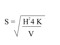
This is the simplist formula to work out and is the 'simplified drain spacing equation':
What does this mean?
Are drainage pipes just installed into an area at a standard spacing of 5m or 10m, or any other figure? No. Obviously much will depend upon how well the existing soil can remove water through its profile. A very sandy soil will be, in general, much better than a heavy soil at removing water.
So, to determine an appropriate spacing for pipes in a given area, the formula shown above is used:
- S is the Spacing of the drainage pipes, which is to be determined by the formula;
- H² is the square of the depth of topsoil. For example, if the depth of topsoil is 250mm then the figure that would be inserted here is 250 x 250 = 62,500. The whole of this profile is used as the route for the water to move to the drains;
- 4 is a constant that is required within the formula;
- K is the hydraulic conductivity of the topsoil, for example, this might be 12mm per hour;
- V is the design rate in mm per hour. 2mm per hour might be an appropriate minimum rate for general sports areas, whilst 20-25mm per hour might be required by premier facilities (this high rate would only be achieved by high specification designs, not basic pipe-drain designs).
The design rate will also depend upon the rainfall of the particular climate for the location of the facility. This will take into account the likelihood of heavy downpours etc., to determine what is to be a realistic design rate.
Completed Example
An amenity area which is occasionally used for casual football is to have pipe-drains installed. What might the spacing be, given the following information?
- The depth of topsoil (H) has been measured to be 250mm throughout the whole area;
- The hydraulic conductivity (K) of the soil has been measured at 18mm per hour;
- The design rate (V) for this general area is to be 0.5 mm per hour (equivalent to 12mm or ½ inch per day).
Putting these figures into the relevant formula produces the following result:
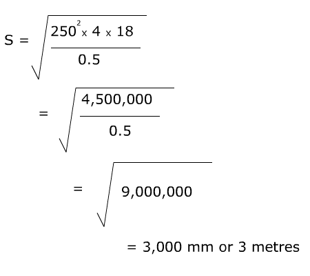
In this example the drainage pipes would have to be laid at no more than 3 metre spacings. Whilst this is a sufficient spacing to remove water within the soil profile, it may not address the problem of ensuring adequate vegetative cover is retained between the pipe spacings.
Much will depend upon how the amenity area is managed, in particular how usage of the area is controlled.
To work out your own examples, use our specialist calculator for determining drain spacings.
Slit Spacing (Two Tier System)
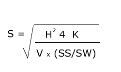
This is a little more complex formula; however, if it is approached in a methodical way then it is easily solved.
The slits are used as the means of transferring the water to the pipe drains. The hydraulic conductivity of the existing topsoil is ignored in this calculation, usually because the actual measured figure would be quite negligible and would contribute little to the removal of water, hence the need for a drainage system which effectively bypasses the soil profile.
What does this mean?
Where the existing soil is inappropriate for a pipe drainage system alone, then the next level of design is probably needed.
This is by installing a slit system over drainage pipes.
To determine an appropriate spacing for pipes (which at the same time is actually the maximum slit length before a slit has to discharge into a pipe) in a given area, the formula shown above is used:
- S is the maximum length for a slit, is to be determined by the formula;
- H² is the square of the depth of permeable fill within the slit. This may be just sand or gravel, or a combination of sand over gravel;
- 4 is a constant that is required within the formula;
- K is the hydraulic conductivity of the permeable fill within the slit. Where there is a combination of material within the slit, then an average K reading is calculated (see below);
- V is the design rate in mm per hour. 2mm per hour might be an appropriate minimum rate for general sports areas, whilst 20-25mm per hour might be required by premier facilities. The design rate includes the ratio of slit spacing to slit width.
- SS is how far each slit is spaced out from another slit, i.e. the Slit Spacing;
- SW is the width of the slit, i.e. Slit Width.
The design rate will also depend upon the rainfall of the particular climate for the location of the facility, which will take into account the likelihood of heavy downpours etc., to determine what is to be a realistic design rate, as well as the quality of the required facility.
Average Hydraulic Conductivity of Two Materials Within a Sand-Gravel Slit
The average hydraulic conductivity figure is calculated and then used within the above formula for determining maximum length of slit run.
The formula for determining the average hydraulic conductivity is as follows:
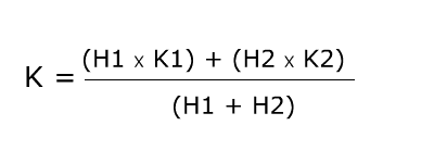
- H1 is the depth of permeable fill for the first material, in the example below this is 100mm of sand;
- H2 is the depth of permeable fill for the second material, in the example below this is 150mm of gravel;
- K1 is the hydraulic conductivity of the first permeable material (i.e. 400 mm per hour for sand);
- K2 is the hydraulic conductivity of the second permeable material (i.e. 50,000 mm per hour for gravel);
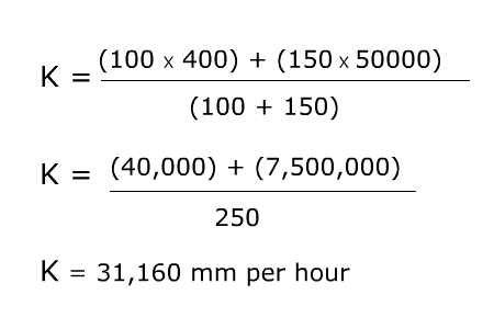
Completed Example
A football pitch is to have a sand-gravel slit drainage system installed. What is the maximum length of slit run before the slit must discharge into a pipe, given the following information?
The slit is to have 150mm of gravel surmounted by 100mm of sand.
- The depth of permeable fill (H) in a slit is 250mm;
- The average hydraulic conductivity (K) of the permeable fill in the slit is 30,160mm per hour (using the example given above);
- The design rate (V) for this general area is to be 12 mm per hour;
- The slit spacing (SS) is to be 1,000mm (or 1 metre);
- The slit width (SW) is to be 50mm.
Putting these figures into the relevant formula produces the following result:
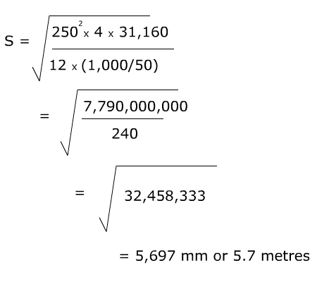
In this example the length of sand-gravel slits would be no greater than 5.7 metres before discharging into a pipe drain.
To work out your own examples, use our specialist calculator for determining the length of sand-gravel slits.
References and Further Reading
- Gooch & Escritt, (1975),'Sports Ground Construction - Specifications', NPFA
- Adams, W.A. & Gibbs, R.J. (1994), 'Natural Turf for Sport and Amenity: Science and Practice'
- Rowell, D.L. (1994), 'Soil Science: Methods & Applications'
- Stewart, V.I. (1994), 'Sports Turf Science, Construction and Maintenance'
